DATA CENTER STRUCTURAL GRID CEILING
Structural Ceiling Grid For Data Center Overhead Utility Distribution
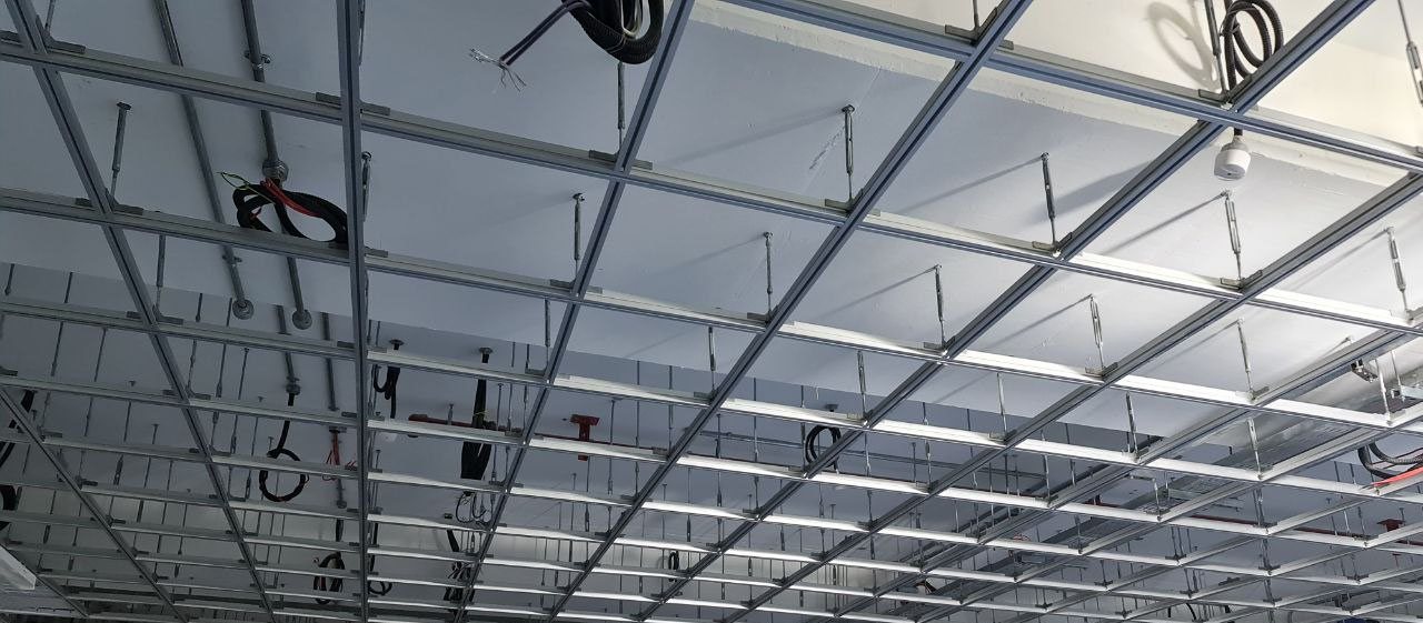
Data Build Technologies offers Data Center Structural Ceiling solution from the industry leader GORDON Inc. completely eliminates the challenges experienced by the Data Center design team for suspending heavy overhead mechanical and electrical services with traditional lightweight acoustic false ceilings. Highly versatile and robust Gordon Structural Ceiling System used in medium, large & hyperscale Data Center facilities to meet the complex challenges of current requirements
In order to meet current Data Center Ceiling capacities, Structural Ceilings must provide the following features:
- The ceiling design serves the dual purpose of both a Drop Ceiling System and structural Ceiling Suspension System for overhead utility distribution.
- The Ceiling Suspension System provides an attachment or suspension platform for containment barriers, partitions, or surface mounted equipment
- Greater installation and routing flexibility of distribution systems and partitions are required to adapt to changes in the Data Center market.
- Totally accessible overhead Data Center Ceiling Suspension System allows for simple expansion, upgrade or distribution system change
- Ceiling Suspension System components must be non-progressive and removable, without compromising the structural integrity of the installed Ceiling System.
Current Data Center Ceiling Design
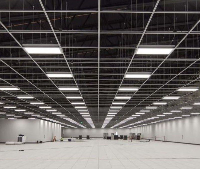
Today’s data centers require Ceiling Suspension Systems to provide both flexibility and increasingly greater load carrying capabilities for end users to support operations today and in the future.
The current trend of eliminating raised floors will require greater loads to be transferred to the Ceiling Suspension System in order to carry more service equipment. For this reason, it is important to understand the key features required of the Data Center Ceiling Suspension System and how to determine which Suspension System to best for your project’s design loads.
Meeting Data Center Design Specifications
A properly designed Ceiling Suspension System eliminates the need for separate strut grids to handle overhead distribution suspension with an acoustical tile drop ceiling below the struts.
Design parameters and loading requirements vary between Data Centers. For this reason it is important to understand how loading is applied to the Ceiling Suspension System and how to determine which Ceiling Suspension System is right for your project.
Load Definitions
There are two types of Loads applied to the Data Center Ceiling:
1) Static Point Loads; and
2) Uniform Loads.
Shown below is a definition for each type of Load and an example of how this applies to a Data Center Suspension System.
Static Point Loads
A Load or Force applied to a specific point on a supporting structure.
Example:
A cable tray may be suspended from a Ceiling Suspension System every 1200mm. The cable tray’s suspension points connected to the Ceiling Suspension System is where its Static Point Loads are applied. The total load over the 1200mm of the cable tray is transferred to the Ceiling Suspension System at these specific points.
Uniform Loads
A Load or Force evenly distributed along a supporting structure.
Example:
A lay-in light fixture distributes its weight (Load) along all suspension tee profiles that it is contacting. The total Load applied to the Ceiling Suspension System is evenly distributed over the entire LM of the suspension tees and not applied to only one point.
Design Attributes
Load bearing ceiling design engineered to support direct suspension of overhead cable distribution and containment barriers
All ceiling extrusions have a continuous 3/8-16 (M-10 for metric) thread boss for attachment and/or suspension at any location
Die cast intersection connectors join the extruded aluminum grid members and provide an attachment point for 4’ x 4’ (1200mm x 1200mm) suspension from building structure
Perimeter ceiling trim can be fixed or floating for seismic compliance
Standard clear anodized finish, with options of black or white powder coating
Meets Standard BS EN13964:2014
Meets Standard ASTM E580